H. Bushouse
Space Telescope Science Institute, 3700 San Martin Drive,
Baltimore, MD 21218
M. Rosa and Th. Mueller
Space Telescope--European Coordinating Facility, European Southern
Observatory, Karl-Schwarzschild-Str. 2, D--85748 Garching, Germany
The HST Faint Object Spectrograph (FOS) uses blazed, ruled gratings and detectors that are sensitive over wide wavelength ranges. Therefore the FOS is subject to scattered light which has its origin in the diffraction patterns of the gratings and the entrance apertures, as well as the micro-roughness of the ruled gratings. This becomes a significant problem when red stars are observed at short wavelengths where the spectrum is often dominated by scattered red photons.
The analysis of laboratory and in-flight FOS data indicates that the instrument is very close to the performance anticipated from ideal optical surfaces. Therefore, the contamination of observations by scattered light can be predicted with reasonable accuracy.
The program bspec has been developed to model the dispersion and diffraction of light in the FOS with an accuracy sufficient for the estimation of scattered light contamination in observed FOS data. The program was developed and is maintained in the MIDAS environment and it was recently ported to the IRAF environment. bspec takes an input spectral distribution and disperses it into the most significant spectral orders---using the equations of blazed gratings and the grating parameters for the FOS---and convolves this multi-order spectrum with a model of the instrumental line spread function (LSF). It is light from the wing of order zero that constitutes a significant portion of the scattered light level seen in the blue wavelength end of first-order FOS spectra.
The spectra produced by bspec, which includes the intrinsic spectrum of the source as well as the predicted intrinsic plus scattered light spectrum, can be compared with FOS observations in order to determine the relative amount of scattered light contained in observed spectra.
The bspec program takes as input a spectral distribution of count rates
which is dispersed into the most significant spectral orders (e.g., -5 to
+5) using the equations of blazed gratings and the known parameters of the
FOS gratings.
Light from the wing of order zero constitutes a significant component of the
scattered light in the blue part of the first order spectra imaged onto
the detector. The amount of zero order light is determined in bspec
as the residual flux not being distributed into higher orders. By
comparison with more rigorous models, we find it sufficient to include
orders up through 5. Even for stellar spectra as late as M5, the fractional
improvement of including higher orders is below  .
.
The spectral shape in each order is the product of the input spectrum and the blaze function for a given order. The resultant multi-order spectrum is convolved with a model of the line spread function (LSF) which represents the effects of diffraction at the entrance aperture, the collimator, the grating and the detector faceplate, and includes a flat component to simulate micro-roughness and dust particle scatter.
In order to ensure that all significant light is collected and redistributed
by both the grating equations and the convolution with the LSF, the
computation is performed over a range of diffracted angles much larger
than that seen by the actual detector.
The red and blue FOS detectors both cover the range  to
to  degrees
from the grating normal.
The computations in bspec typically cover the range -10 to +35
degrees in diffracted angle, which includes all orders from zero to five.
degrees
from the grating normal.
The computations in bspec typically cover the range -10 to +35
degrees in diffracted angle, which includes all orders from zero to five.
In practice, correcting observational data for scattered light must be done before the count rate spectra are transformed to absolute fluxes. The bspec program is therefore intended to produce output data that are in units of counts per pixel, which then requires that the input data also be in this form. Calibrated spectra must be prepared for use in bspec by scaling by the sensitivity and transmission of all the HST and FOS optical components, except for the grating blaze function which is computed and applied within bspec. In particular the conversion from flux per unit wavelength to counts per pixel has to be made before using in bspec.
To make this job easier a program called countspec has been developed in IRAF/STSDAS which will convert a flux calibrated spectrum of any object into a count rate spectrum. The countspec program uses the known throughputs and sensitivities of the HST and FOS optical components---as contained in the HST Calibration Data Base System (CDBS)---to perform this conversion.
The bspec program, in both the MIDAS and IRAF environments, uses tables for all input and output data. The countspec program (only available in IRAF/STSDAS) also uses tables. The input and output tables for countspec and the input table to bspec are simple two-column tables of wavelengths and fluxes (or counts). The output table produced by bspec contains several columns of data including wavelengths and dispersed counts, both with and without scattered light, and the grating blaze function.
For illustration let the target spectrum be the model atmosphere for the the solar-like star 16 Cyg B, which we wish to compare with an observed spectrum of this star obtained using the FOS blue detector, the G190H grating, and the 1.'' 0 round aperture.
First, we prepare the model spectrum---which is in absolute flux units---using the countspec task to convert the model data to a count rate spectrum. The calibrated model data are contained in table cyg16b.tab and the count rate spectrum will be written to table counts.tab. We run countspec as follows:
cl> countspec cyg16b fos,1.0,g190h,blue counts.tab
The second argument, ``fos,1.0,g190h,blue", specifies the desired instrument observing mode.
Second, we run bspec, using the table counts.tab as input, to compute a predicted scattered light spectrum. The output from bspec will be written to table scatter.tab. It is only necessary to specify the input and output table names and the detector and grating names. Appropriate default values for the grating and LSF parameters will be chosen based on the selected detector/grating combination. We run bspec as follows:
cl> bspec counts.tab scatter.tab blue g190h
Figure ![]() shows the results of bspec computations for the star
16 Cyg B as observed with the FOS blue detector and G190H grating.
The lower curve in Figure
shows the results of bspec computations for the star
16 Cyg B as observed with the FOS blue detector and G190H grating.
The lower curve in Figure ![]() shows
what would be an ``ideal" spectrum as observed by an unphysical
instrument that relates wavelengths one-to-one with diffracted angles.
The upper curve (offset vertically by a factor of 10) shows the
``model observations'' computed by bspec, i.e., the
intrinsic spectrum dispersed by the blazed grating and further convolved
with the scattering imposed by the entrance aperture, the ruled surface
of the grating and a minute amount of dust on the optical surfaces.
Orders -5 to +5 were computed but only orders 0 to 2
are shown in the figure.
Note that the real detector covers only the wavelength range indicated
by the horizontal bar near 2000Å.
shows
what would be an ``ideal" spectrum as observed by an unphysical
instrument that relates wavelengths one-to-one with diffracted angles.
The upper curve (offset vertically by a factor of 10) shows the
``model observations'' computed by bspec, i.e., the
intrinsic spectrum dispersed by the blazed grating and further convolved
with the scattering imposed by the entrance aperture, the ruled surface
of the grating and a minute amount of dust on the optical surfaces.
Orders -5 to +5 were computed but only orders 0 to 2
are shown in the figure.
Note that the real detector covers only the wavelength range indicated
by the horizontal bar near 2000Å.
The shape of the zero order peak in Figure ![]() reflects the actual LSF.
The far wings of this LSF carry light from the peak of the original
spectral distribution into regions where the target spectrum, filtered
by the total throughput of the optical elements and the detector
efficiency, produces few intrinsic counts.
In addition, this LSF moves photons from the zero order peak into the
adjacent parts of the first order seen by the detector.
reflects the actual LSF.
The far wings of this LSF carry light from the peak of the original
spectral distribution into regions where the target spectrum, filtered
by the total throughput of the optical elements and the detector
efficiency, produces few intrinsic counts.
In addition, this LSF moves photons from the zero order peak into the
adjacent parts of the first order seen by the detector.
Figure ![]() shows an actual observed FOS spectrum of 16 Cyg B overlaid
with the ``ideal" and the ``model" observations from Figure
shows an actual observed FOS spectrum of 16 Cyg B overlaid
with the ``ideal" and the ``model" observations from Figure ![]() .
The observed spectrum is offset vertically for clarity.
For a solar-like spectrum, the scattered light component ranges between
1--99% of the observed signal in the FOS blue G190H mode.
.
The observed spectrum is offset vertically for clarity.
For a solar-like spectrum, the scattered light component ranges between
1--99% of the observed signal in the FOS blue G190H mode.
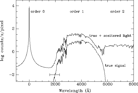
Figure: FOS blue G190H count rate spectra for a G5V model atmosphere.
Original PostScript figure (67 kB)
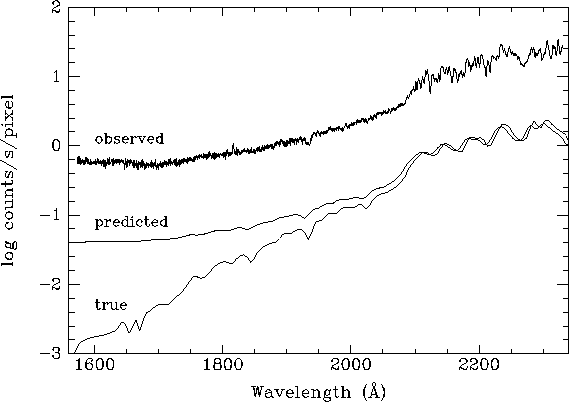
Figure: FOS blue G190H data for the G5V star 16 Cyg B.
Original PostScript figure (58 kB)