D. C. Wells
National Radio Astronomy Observatory, 520 Edgemont Road,
Charlottesville, VA 22903-2475
NRAO has developed a laser ranging system which will be used to measure the active surface of the GBT (Green Bank Telescope) and to measure the orientation of the structure in order to improve the pointing. Some of the ray paths between the laser rangefinders and the retroreflectors are sometimes blocked by the structural elements of the GBT. The author conjectured that visualization software could be an aid in planning placement and operational strategy for the rangefinders and retroreflectors.
The output from the MSC/NASTRAN structural model of the GBT was loaded into the AVS (Advanced Visual Systems) installation in the Charlottesville image processing laboratory, using ``UCD Builder'', an interactive Motif module for importing FEA and CFD data into AVS, which NRAO purchased from SciViz, Inc. (Concord, MA). The AVS software was configured, using its graphical programming tool, to render images of the structure. The azimuth and elevation of the models could be controlled. Objects could be introduced to represent laser rangefinders on the ground around the GBT. The AVS ``camera'' could be commanded to look from any location in the scene toward any another location.
The images produced by the AVS ``geometry viewer'' are in full color, at high resolution. In this paper, we can show only selected images, and only in monochrome.
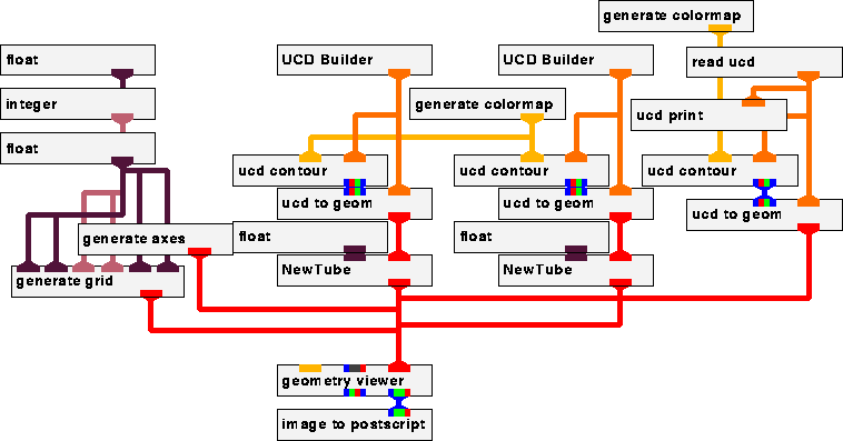
AVS is controlled by a graphical interface.
Named boxes represent modules (programs), and they are connected by
pipes, with the color code indicating the types of the data being
passed from module to module. In the network shown in
Figure ![]() , two different structural models (the alidade
structure and the tipping structure) are being read by the two
executions of the ``UCD Builder'' module, which converts NASTRAN
output files to AVS ``unstructured-cell-data'' (UCD).
, two different structural models (the alidade
structure and the tipping structure) are being read by the two
executions of the ``UCD Builder'' module, which converts NASTRAN
output files to AVS ``unstructured-cell-data'' (UCD).

Figure: The AVS Network.
Original PostScript figure (20 kB)
Module ``read ucd'' reads a data file which describes a set of cubical objects which represent laser rangefinders. Several generator modules add axes and a grid. The outputs of these pipelines are combined as input to the ``geometry viewer'', which renders the imagery. AVS has a graphical editor tool with which the network can be modified interactively; this is the toolkit-plus-visual-programming paradigm which is used in several other scientific visualization systems (e.g. Khoros and IBM's Data Explorer) in addition to AVS.
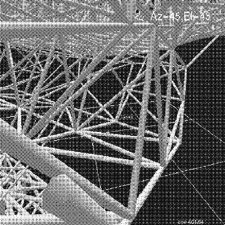
In Figure ![]() , the GBT model is pointing northeast,
resting on the grid of 25 m squares.
, the GBT model is pointing northeast,
resting on the grid of 25 m squares.

Figure: Viewing a Rangefinder from an Elevation Bearing.
Original PostScript figure (1594 kB)
The spot marked ``laser'' is a 1m cube 1.5m above the ground, 74m from the pintle bearing, and about 90m from the ``camera''. The camera is looking from the neighborhood of one of the alidade elevation bearings toward a single rangefinder on the ground. The simulated ``rangefinder'' is visible between the beams of the box structure which carries the backup structure and the feed arm of the GBT. The beams are being approximated by cylinders (using a version of the AVS ``tube'' filter), and the closeup view of the end of one of the principal beams of the alidade demonstrates that the cylinders are hexagonal. The sizes of the hexagonal cylinders of the alidade and tipping structures are independently controllable, and are about 0.9m and 0.4m in this image. It appears that this potential ray path would have a duty cycle of at least 50% while the GBT is tracking.
Color GIFs of GBT visualization images are available. The first is an overview of the telescope model as seen from several hundred meters distance and a height of about 100m. There are 18 cubical objects in the scene, with sides 20inches (0.5m) long. The telescope is pointing at the zenith, and is resting on a grid with a spacing of 1000inches (about 25m). The second scene is an oblique view of the feedroom area from below. The prime focus boom and the subreflector actuator model are above the room, and there are four 0.5m cubes on the edges of the roof of the feedroom, representing suggested locations for rangefinders. The third scene shows a side view of the feedroom, as seen from a point at about the same height as the room. In this scene the two cubes at the rear corners of the feedroom represent proposed locations for rangefinders. The AVS ``camera'' was moved to these cube locations and pointed toward the big primary mirror in order to examine the field-of-view (which is partially blocked by the feedroom) as seen from these locations. It was possible to confirm that the two rangefinders, operating together, will be able to view the entire mirror from the locations shown in this scene.
An important specification of the GBT is that the edge of the beam formed by the primary mirror should clear the feedroom by at least 20 cm, in order to eliminate sidelobes produced by scattering. In order to check this feedroom-to-primary clearance condition and to check that two proposed rangefinders would also be clear of the beam, the camera was commanded to look almost straight down from the tip of the prime focus boom (i.e., the prime focal point of the primary), toward the roof of the feedroom and the inner edge of the big dish. The fact that the beam was not clear in the visualization scene led to an engineering review of the detailed construction drawings to assure that the as-built telescope will indeed have a clear beam. (The geometry of the feedroom as used in the structural model, and therefore in the AVS rendering, was a simplified abstraction.) In the author's opinion, this important case justified the money and effort expended to make the AVS visualization software work with the GBT structural model.